GROMACS version: 2025.2
GROMACS modification: No
Hello everyone. I recently started using GROMACS. So, I have a question. I was following the protein-ligand complex tutorial from the mdtutorial site. During solvation step they used 1.0 Å as the distance between protein from the box edge. On the side I was also reading about periodic boundary condition and how cut-off radius is used to define the box size. But didn’t find any literature about how to do the calculation.
I’m currently working on a antithrombin III pdb file. I am using CHARMM 36 force field. I found through a AI deep search that recommended distance between protein and box edge is 1.2 Å. But if possible I want to keep distance specific to the protein.
I was hoping someone could help me understand how the calculation is done. Also, whether 1.2 Å default distance would be good enough for my simulation.
The cut-off radius for vdW and Coulomb forces generally depends on the force field development, and for common force fields for bio sims (like Amber or CHARMM36) is around 1 to 1.2 nm.
Usually, when you build a box of solvent with a protein you would want to be sure to avoid PBCs artifacts, for example a side of a protein connecting with itself across boundaries. At the same time, it would be better to have enough space to have in principle a region of molecules that is not affected by the same object across boundaries. Think about a protein separated from its image by just a couple of water molecules, barely a solvation shell. It’s clear that the dynamics of these molecules will be highly influenced by the protein on one side and by the same PBC image of the protein on the other. While to an extent PBCs effects will be always present, a good rule of thumb to minimize them is to have a box where the protein is separated by AT LEAST the electrostatics cut-off from its boundaries.
So, the fact the numbers used are different is not important, as long as this rule of thumb is followed. Most likely these two systems used different cut-offs and so the box set up was updated accordingly. Use the value consistent with your force field of choice. Please note that this also means that there is no upper boundary for this number, just a lower one, as having several nm of water separating two images is, if anything, just better. However, the lowest number is used in the box generation to have the box as small as possible and so minimize the atoms number in the box and have faster sims. Personally, I stick to ~1.5 nm just to be sure. Also, consider that this calculation is done on a static structure coming probably from a crystal pdb. The protein will relax and wobble, so the spacing should be actually adjusted in terms of what is the expected behavior of the protein, e.g., if it has a large loop that will detach and wobble then the box will need to be larger to accommodate these degree of freedom.
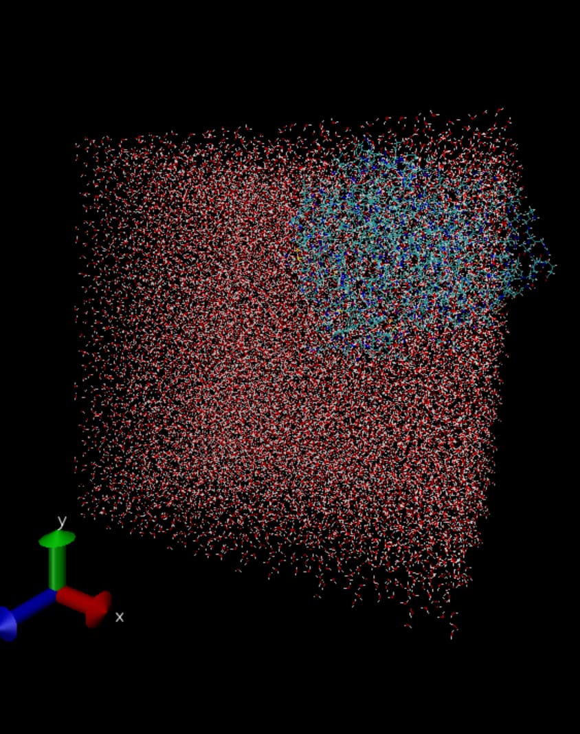
Hi @obZehn Thank your help. I got it that I have to use cutoff radius depends on the force field development. I tried to conduct solvation with a dodecahedron and kept the cut-off radius as 1.2 nm. But a portion of the protein is outside the box. I tried to center it by adding -c after cutoff radius but still it was in the same position. I tried using AI to hep me solve the issue but it says that it is a PBC artifact.
I can’t find any way to resolve the issue. Can you help with this issue?
Yes, it is indeed a PBC visualization “artifact”, in the sense that that’s just how the box is represented in its unit cell representation. In MD we use (basically always) PBCs to avoid the existence of boundaries and imitate an infinitely extended bulk environment. As such, your protein is not really outside of the box, but is actually still in the bulk solution. I highly suggest you to do some reading on PBC, for example here, as these are paramount in MD and one of the core concepts to know.
You can fix the visual representation with tools such as gmx trjconv.